Concept
互動裝置的開發經常需要無線通訊功能。有線連接雖然穩定,但會被線材長度限制,影響裝置的擺放位置和使用場域。無線通訊可以打破這個限制,讓互動裝置有更大的部署彈性。
無線模組的選擇有藍牙、WiFi、RF模組。藍牙和WiFi需要配對才能通訊,使用前要先設定連線。RF廣播模組不需要配對,發射端直接廣播,接收端在範圍內就能收到訊號。而且RF模組的通訊距離比藍牙和WiFi都要遠,更適合大範圍的互動場域。
要做出遠距離無線系統,通常要把RF模組、微控制器、感測器、顯示器、電源管理等多個模組接在一起。這樣的接線很容易亂,而且技術門檻高,每次做新專案都要重新配線和除錯。
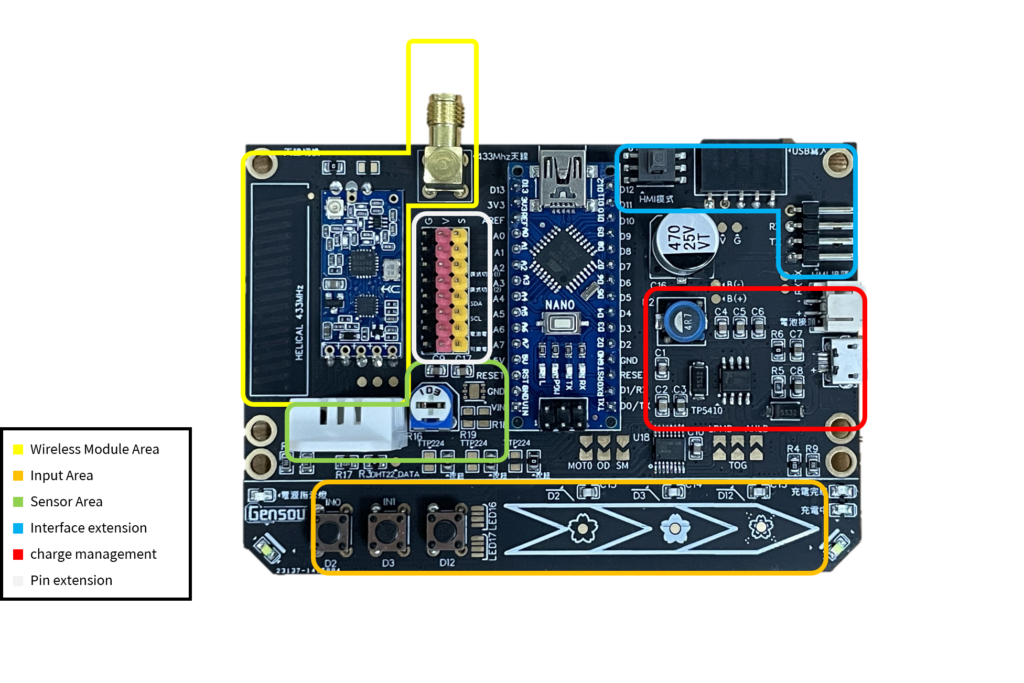
為了降低這個門檻,我設計了IDF_ONE整合板,把這些功能整合到一塊PCB上:遠距離無線通訊(LoRa)、觸控螢幕介面、I/O擴充接腳、溫溼度感測器、電池管理系統。需要做互動裝置的時候,直接用這塊板就能快速建構原型,不用每次都從零開始接線。
Interactive installations often need wireless communication. Wired connections are reliable, but cable length restricts where you can place devices and limits the interaction space. Wireless communication removes this constraint, giving you more flexibility in deployment.
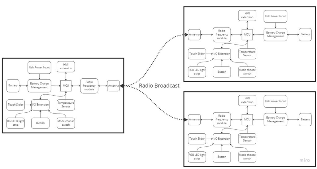
For wireless modules, the common options are Bluetooth, WiFi, and RF modules. Bluetooth and WiFi require pairing before devices can communicate—you need to set up the connection first. RF broadcast modules work differently: the transmitter just broadcasts, and any receiver in range picks up the signal. RF modules also have longer range than Bluetooth or WiFi, making them better suited for large-scale interactive spaces.
Building a long-range wireless system typically means wiring together multiple modules: RF module, microcontroller, sensors, display, power management. The wiring gets messy quickly, and the technical barrier is high. Every new project means re-wiring and debugging from scratch.
To lower this barrier, I designed the IDF_ONE integration board. It combines these functions on a single PCB: long-range wireless communication (LoRa), touchscreen interface, I/O expansion headers, temperature/humidity sensor, and battery management system. When you need to build an interactive device, you can use this board to rapidly prototype without starting from zero every time.
Tech specs
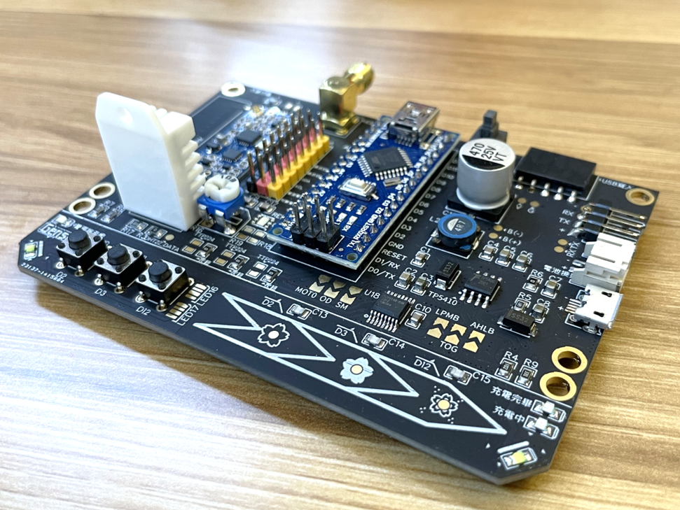
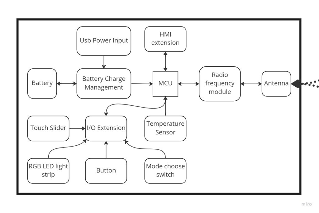
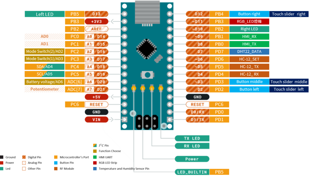
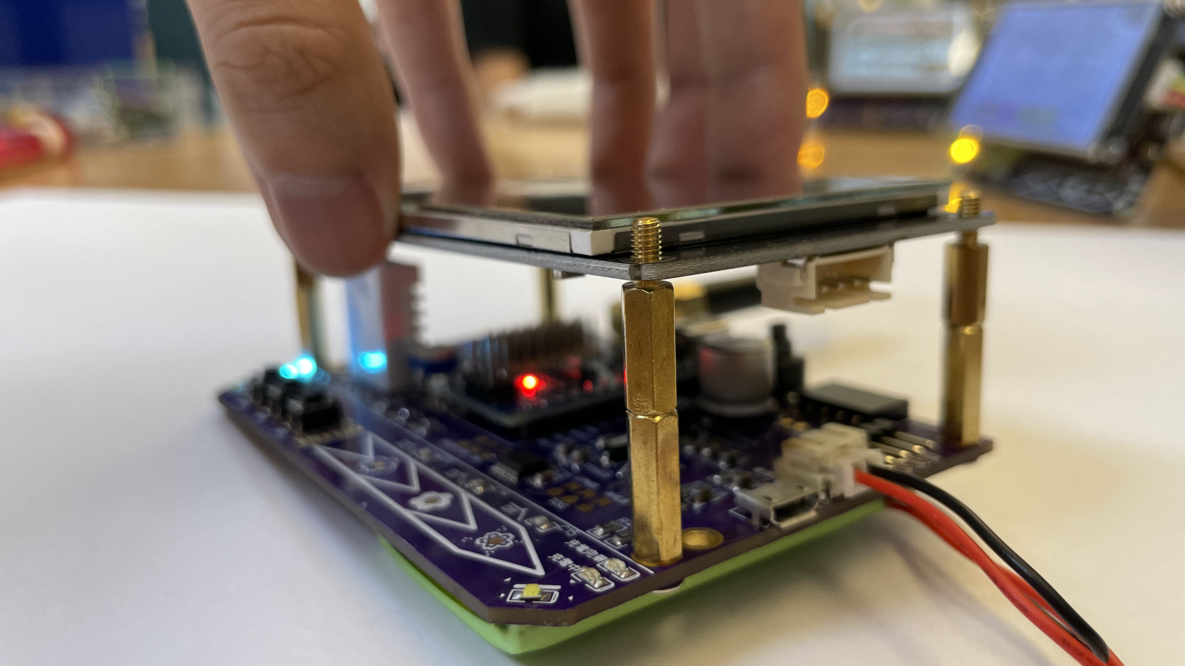
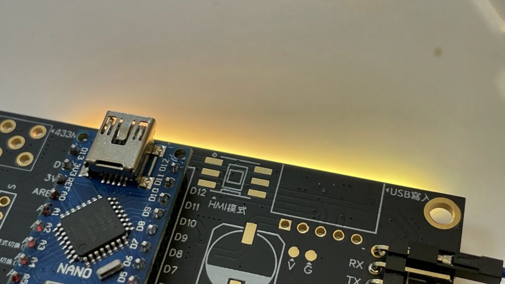
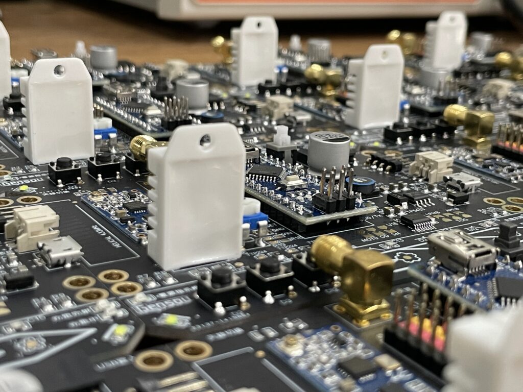
需要將多功能結合在一塊PCB系統板,需要有一個中央處理晶片,處理與溝通控制各模組的功能,這裡使用Arduino進行各模組之間的溝通,與無線廣播模組、I/O擴充、感測器模組、RGB LED strip、HMI擴充進行溝通整合。並且為了使HMI可以直接與系統板以銅柱結合,因此將系統板設計的與HMI大小相同且開孔相同,以利於HMI可以直接組裝在系統板上。
The integration board needs a central controller to coordinate all modules. I used an Arduino Nano as the main controller, handling communication and control logic between the LoRa wireless module, I/O expansion, sensors, RGB LED strip, and touchscreen.
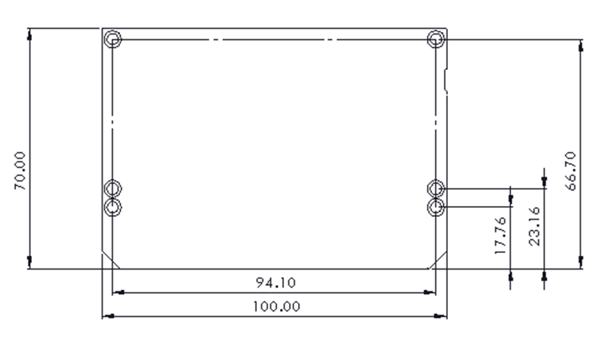
To enable the touchscreen to stack directly on top of the main board as an integrated design, I made the PCB dimensions and mounting holes match the display exactly. The screen mounts on standoffs directly above the board, creating a unified interactive system.

Mode Change Design
Arduino nano的腳位並不夠連接所有的模組,達到整體彙整為一塊系統板的功能,因此將相似的功能利用0歐姆電阻作為切換。
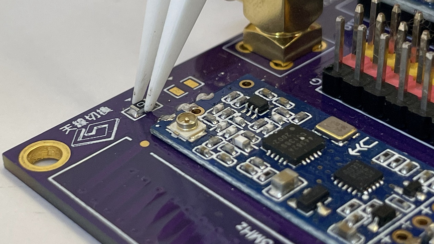
無線廣播通訊模組,須利用天線使通訊距離增加,為了使用方便設計PCB天線與外擴天線並且以0歐姆電阻作為切換。
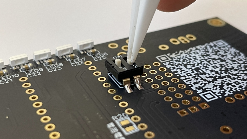
利用切換開關的設計,方便切換系統模式或是開機模式。
Arduino Nano的接腳數量不夠連接所有模組。為了解決這個問題,我用0歐姆電阻當作跳線選擇器,讓某些功能可以共用接腳,需要哪個功能就焊接對應的跳線。
天線設計上,我同時做了PCB走線天線和外接天線座。用0歐姆電阻選擇要啟用哪一個:如果要體積小就用PCB天線,如果要最大通訊距離就接外接天線。
板上也設計了撥動開關,可以切換系統的工作模式和開機模式,不用每次都改程式碼來切換功能。
The Arduino Nano doesn’t have enough pins for all the modules. To solve this, I used 0Ω resistors as jumper selectors, allowing certain functions to share pins. You solder the jumper for whichever function you need.
For the antenna design, I included both a PCB trace antenna and an external antenna connector. A 0Ω resistor selects which one is active: use the PCB antenna if you want a compact design, or connect an external antenna for maximum communication range.
The board also has toggle switches to change the system’s operating mode and boot mode, so you don’t have to modify code every time you want to switch functions.
I/O and Temperature Sensor Extension
-
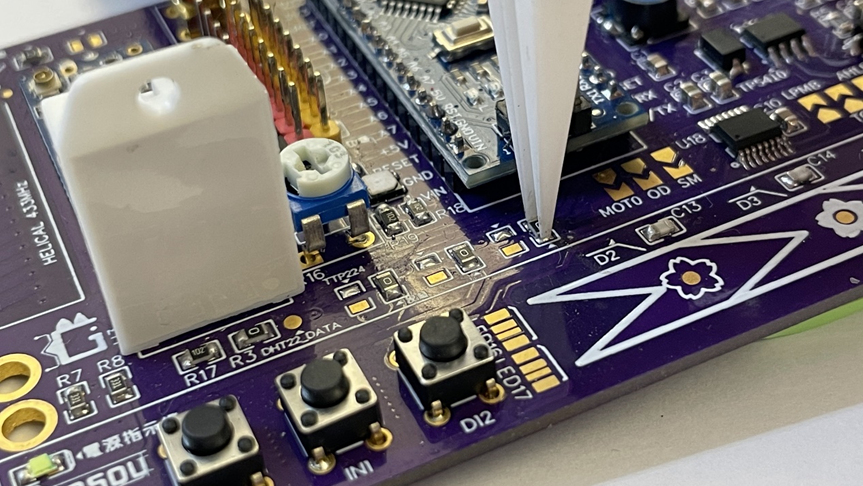
- 板子有一組8pin的I/O擴充排針,可以連接外部感測器或致動器。
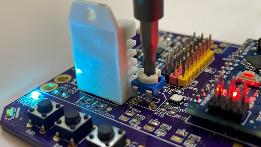
- 內建可變電阻,可以在不改程式碼的情況下調整參數,方便現場微調。
- 板上直接焊了一顆溫溼度感測器(DHT22),讓系統一開始就有環境感測能力,不用額外接線。
-
- The board has an 8-pin I/O expansion header for connecting external sensors or actuators.
- A built-in potentiometer allows on-the-fly parameter adjustment without modifying code—convenient for field tuning.
- An onboard temperature and humidity sensor (DHT22) provides environmental sensing capability right out of the box, no additional wiring needed.
Battrey Charge Management
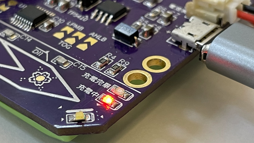
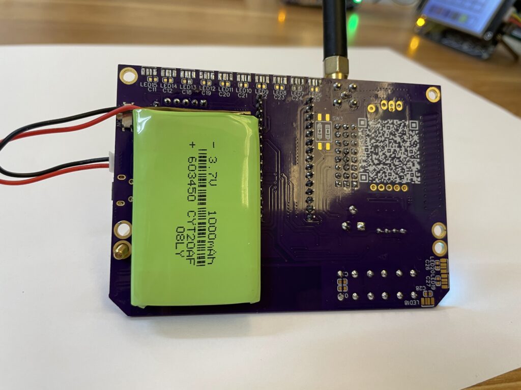
為了做成可移動的無線裝置,電池是必要的。板子使用鋰電池供電,電池管理晶片可以處理USB充電,而且充電的時候系統還能同時運作,不用拔掉電池就能用USB電源直接供電。充電管理晶片有指示燈,可以直接看到充電狀態。
For portable wireless devices, a battery is essential. The board runs on a rechargeable lithium battery. The battery management chip handles USB charging, and the system can operate while charging—you can run the board directly from USB power without removing the battery.The charge management chip has an indicator LED to show charging status at a glance.
Human Machine Interface Extension
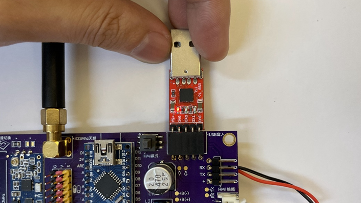
系統板與人機介面是利用USART通訊與燒錄,在系統板中有USART的擴充接點,並且開孔位置與人機介面相同,因此可以直接與系統板連結擴充。
利用USB to TTL 模組與系統板連結,可直接對人機介面燒入。
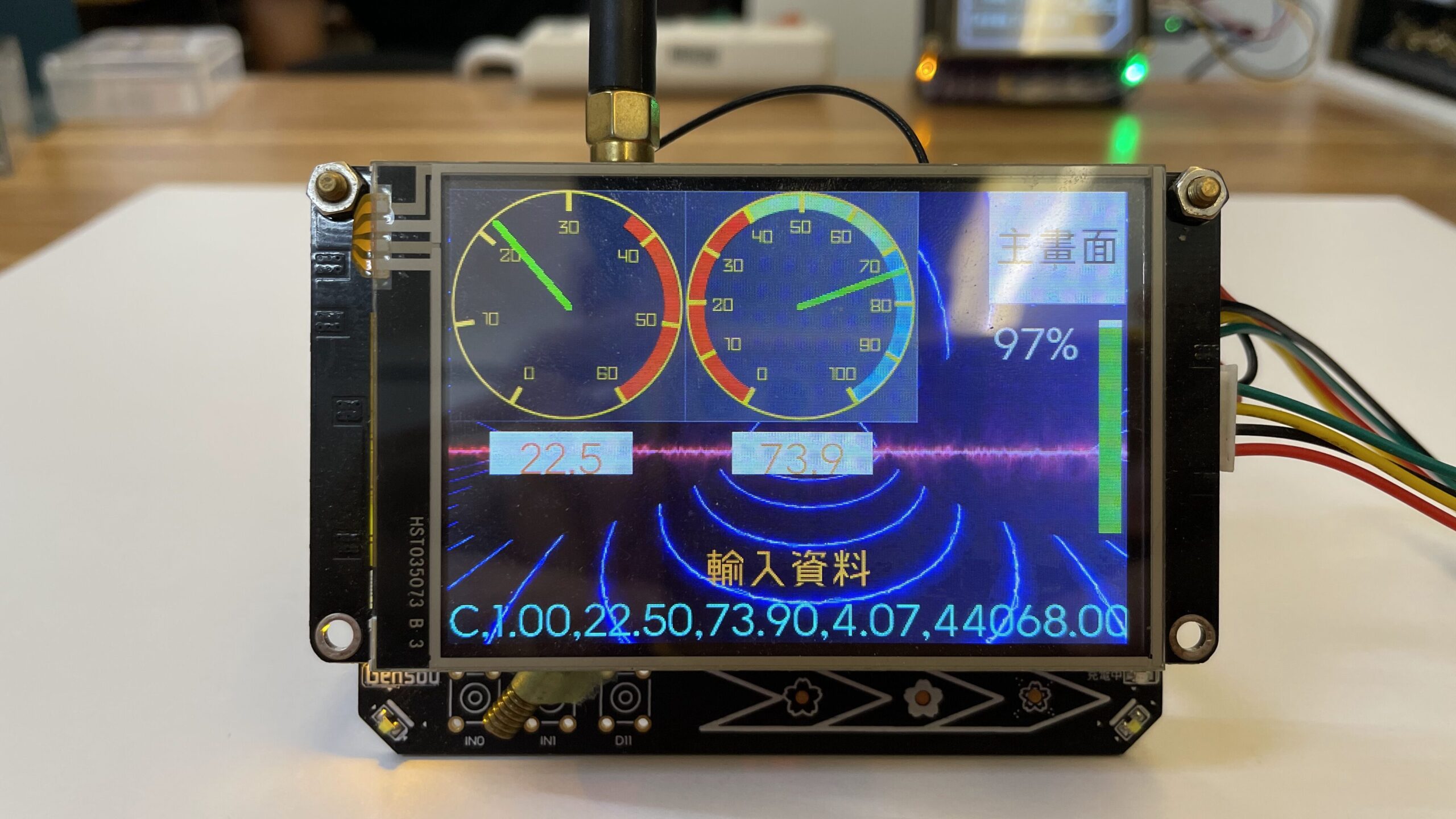
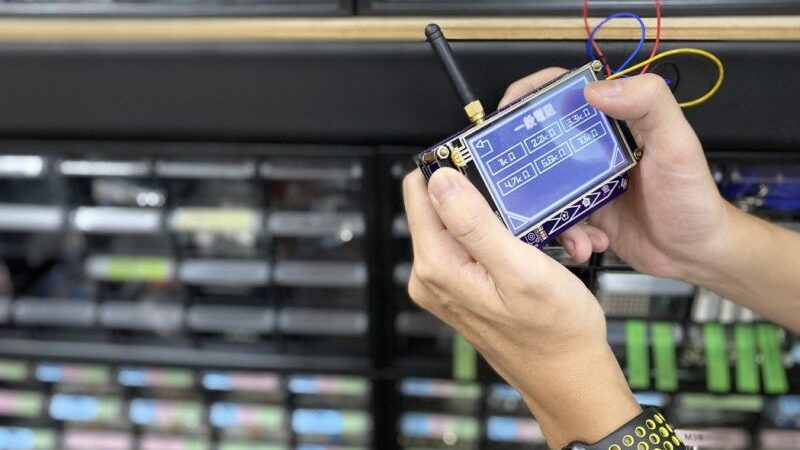
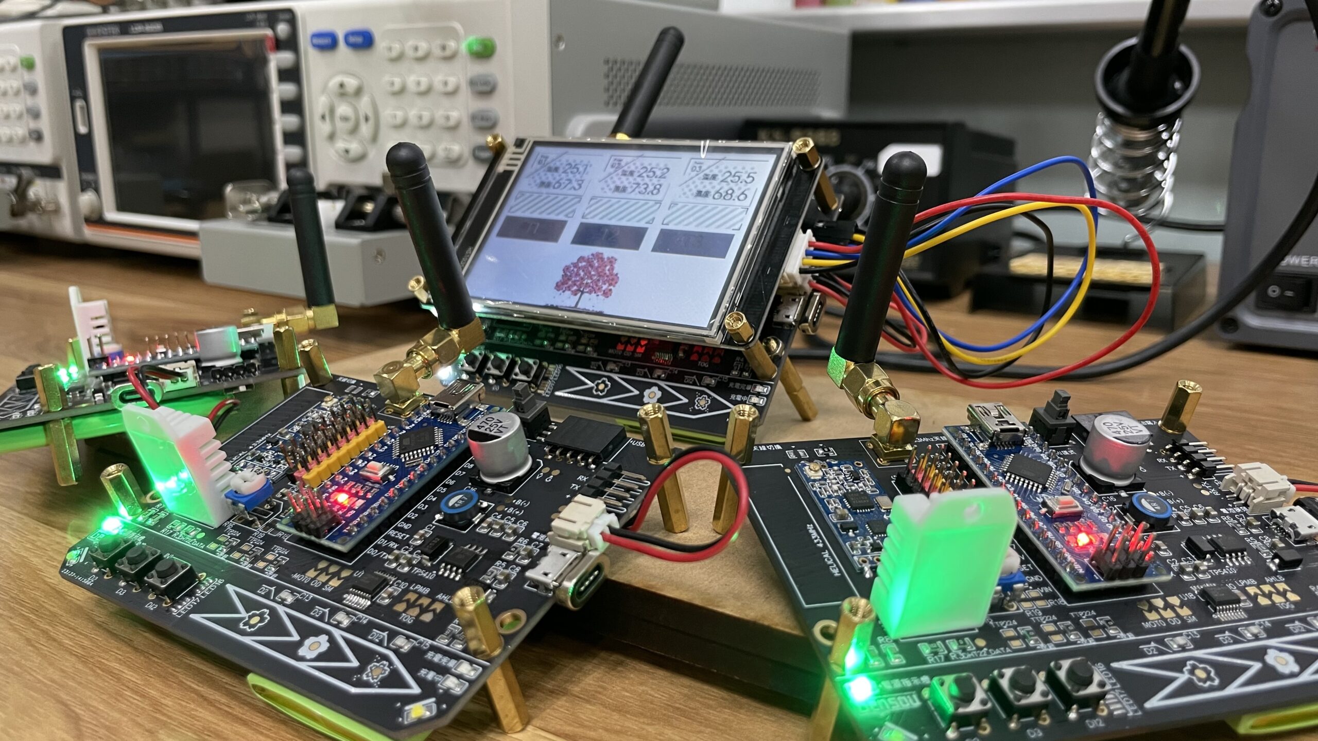
最終畫面人機介面展示,利用無線廣播模組接收其他系統板所感測的溫溼度資訊,並且以圖像化方式顯示。
畫面下方顯示接受字串,並且包含CRC驗證資料。
The system board and the human-machine interface use USART to communicate and program. There are USART expansion pins in the system board, and the hole position is the same as that of the human-machine interface, so it can be directly connected to the system board for expansion.
Use the USB to TTL module to connect with the system board, which can be directly burned into the human-machine interface.
The human-machine interface display on the final screen uses the wireless broadcast module to receive the temperature and humidity information sensed by other system boards and displays them graphically.
The acceptance string is displayed at the bottom of the screen and contains CRC verification data.
RGB LED light strip
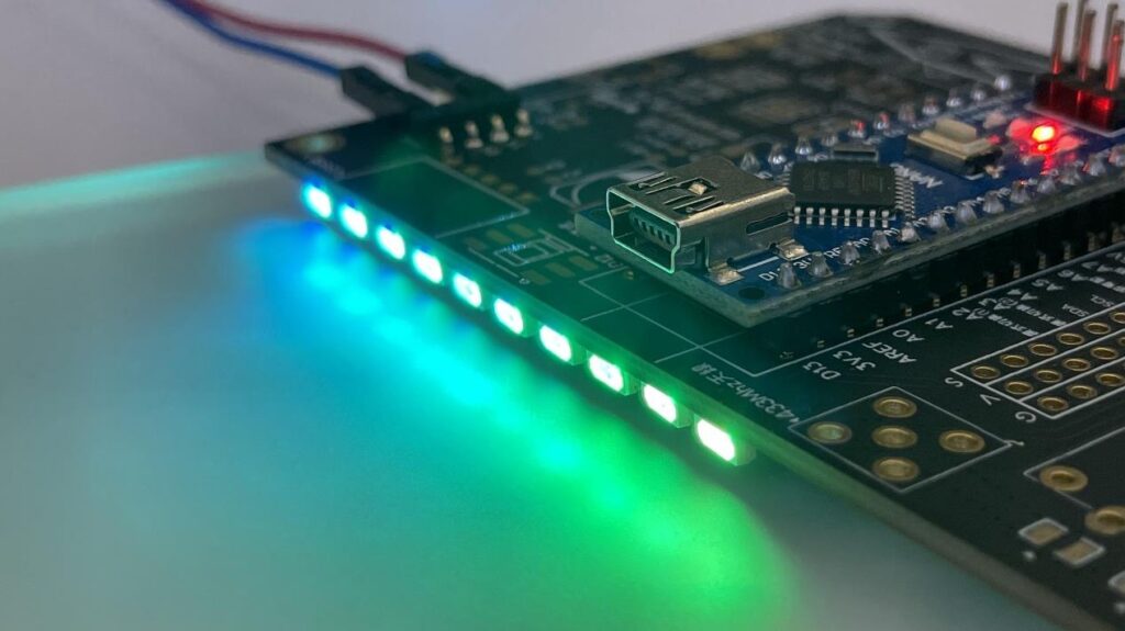
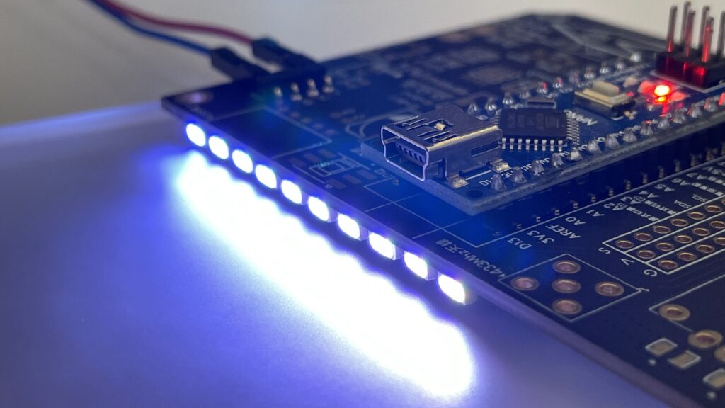
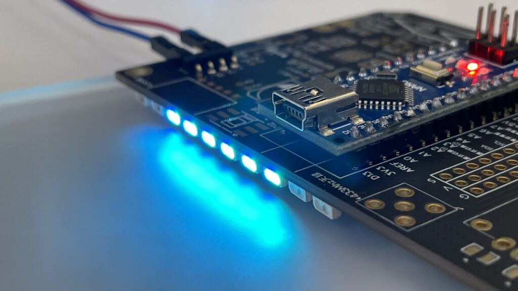
內建的RGB LED 燈條 ,可以利用字串控制的方式,驅動特定顆數RGB LED亮起特定的顏色。
The built-in RGB LED strip can use Data control to drive a specific number of RGB LEDs to light up a specific color.

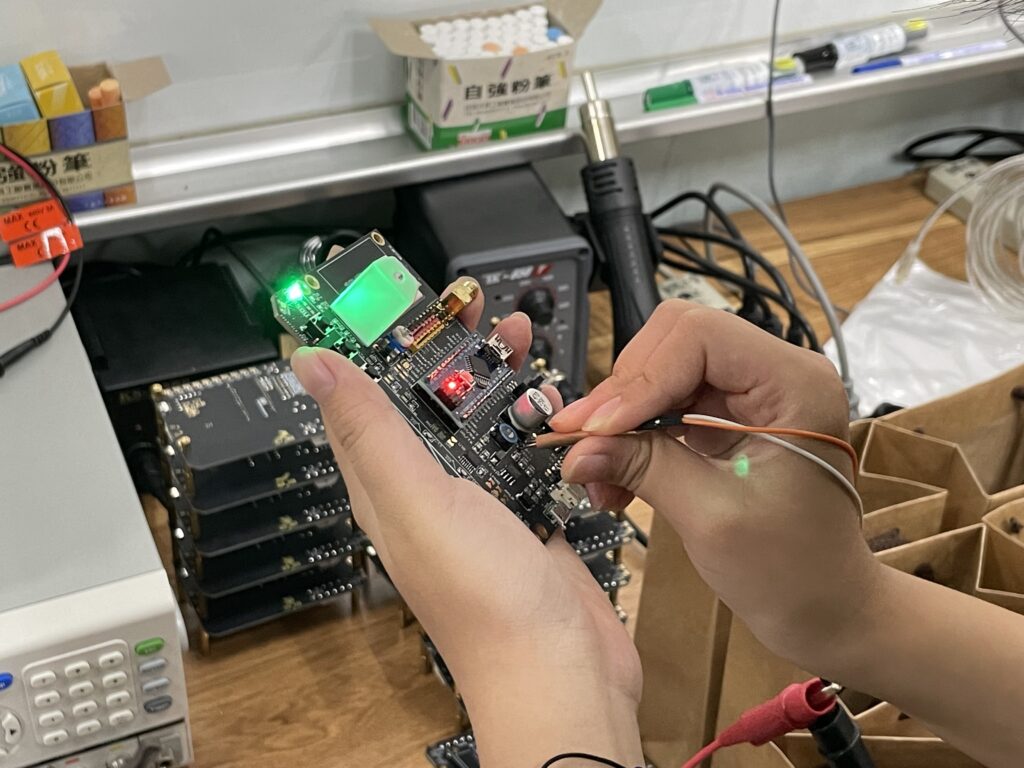
Small Batch Production
-
- 利用網版印刷方式,將錫膏印刷至PCB板上
-
- 並且放置SMD元件至系統板上
-
- 熱板加熱使錫膏融化將SMD元件焊接固定
-
- 焊接DIP元件
-
- 最終以探針供應電源,檢查系統板是否正常運作
-
- Use screen printing to print solder paste onto the PCB
-
- And place SMD components on the system board
-
- The hot plate is heated to melt the solder paste to solder and fix the SMD components
-
- Soldering DIP components
-
- Finally, supply power with a probe to check whether the system board is functioning normally

Use this Board to Finish Project
在作品集內有其他應用這塊系統板的應用專題。
IOT component storage search system
利用無線廣播方式,同時搜尋特定零件在置物櫃的位置,並且以RGB LED燈條顯示零件位置。
Use the wireless broadcasting method to search for the location of specific parts in the locker at the same time, and display the location of the parts with RGB LED light strip.
Temperature and Humidity Sensor System
利用無線廣播方式,接收來自三塊系統版上的溫溼度感測資料,並且顯示在HMI上。通過HMI操作可以指定控制特定一塊系統版上的輸出功能。
Use wireless broadcasting to receive temperature and humidity sensing data from the three system boards and display them on the HMI. Through the HMI operation, the output function on a specific system board can be designated to be controlled.
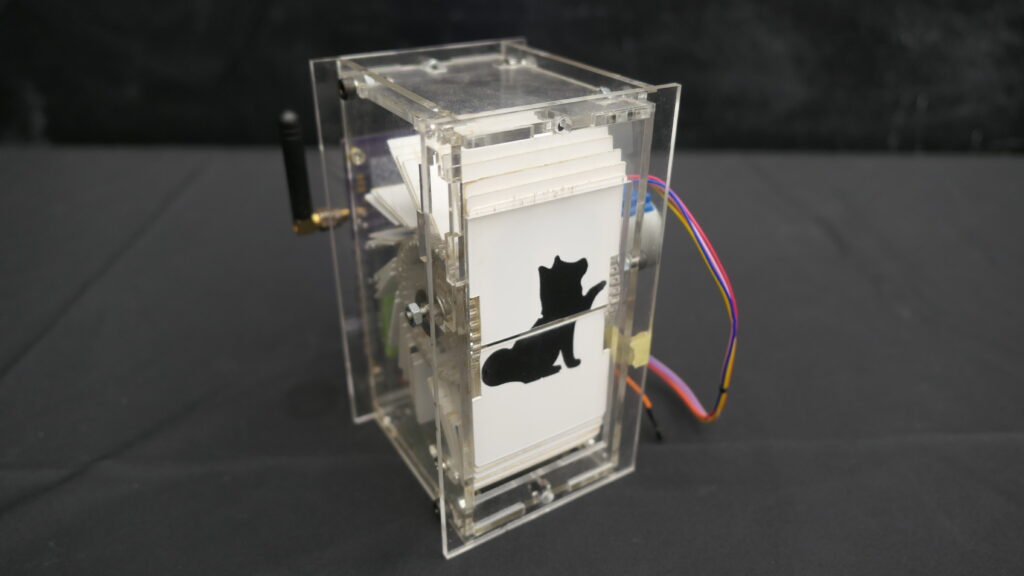
Split Flap Display
利用無線廣播方式,控制翻頁顯示器顯示特定英文或數字的頁數。利用噴漆方式實現了頁面客製化。
Use wireless broadcasting to control the split flap display to display the number of pages in specific English or numbers.
Page customization is realized by spray painting.
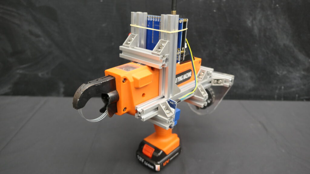
Node Locker
利用無線廣播方式,設計機械手臂與工具頭的物聯網環境。以機械手臂或是HMI發送無線廣播命令控制工具頭實現特定功能。
Using wireless broadcasting, design the IoT environment of the robotic arm and tool head. Use the robotic arm or HMI to send wireless broadcast commands to control the tool head to achieve specific functions.
1 comment
I’m not positive where you are getting your info, however
good topic. I must spend some time studying
more or working out more. Thanks for excellent info I was
on the lookout for this information for my mission.