
Section 1: The Challenge | 挑戰與動機
我們存在於物理世界,但是要接觸到虛擬世界、並且與虛擬世界互動,就需要藉由裝置來進行溝通,來減少物理世界與虛擬世界的距離。這個想法的起源,是我在大學時看到的一則TED演講。
We live in the physical world, but to reach into the virtual world and interact with it, we need devices to bridge that gap – to close the distance between the physical and virtual worlds. This idea started for me back in college when I watched a TED talk.
XR技術能讓我們透過VR眼鏡來獲取視覺與聽覺體驗,但是對於觸覺而言,目前大多數的方法還是停留在使用控制器、用震動的方式來回饋。但是用震動來感受一個物品?聽了其實都覺得很奇妙對吧?
XR technology lets us experience visuals and audio through VR headsets, but when it comes to touch? Most current solutions still rely on controllers that use vibration for feedback. But using vibration to feel an object? Even just saying it sounds kind of weird, right?
震動怎麼模擬觸覺?How does vibration simulate touch?
根據我收集的學術論文,大多的解釋是利用頻率來模擬粗糙度,來呈現滑動時摸到物品表面的觸覺,而這個震動是讓人產生相似粗糙度的錯覺回饋邏輯。這個邏輯很明確沒錯,也是現有技術中便宜的解決方案。
但是在我的研究中,我實際的去抓了一些物理世界的物品,認真地感受並定義了我認為的觸覺回饋應該是什麼樣子。
From the research papers I’ve collected, most explanations say it uses frequency to simulate roughness – giving you the sensation of sliding your finger across a textured surface. The vibration creates an illusion of similar roughness. This logic is clear, and it’s definitely one of the cheaper solutions available.
But in my research, I actually went out and grabbed various real-world objects, really feeling them and defining what I believe haptic feedback should actually be like.
一個實驗:閉眼抓球
An experiment: Grabbing a ball with your eyes closed
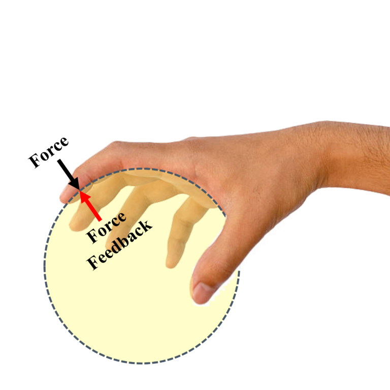
當我把軟式網球抓握起來,我感受到的是來自球的力的回饋,而且我發現到每根手指給我的感受都是不同的,連手指接觸球的角度也都不同。這說明了如果我採用模擬方案、直接貼在手指表面皮膚上,模擬出來的感覺效果會很不真實,因為物理世界的觸覺回饋並不是這樣運作的。
When I pick up a soft tennis ball, what I feel is the force feedback from the ball. And I noticed that each finger gives me a different sensation – even the angle at which each finger contacts the ball is different. This shows that if I just use a simulation approach – directly attaching something to the skin surface of my fingers – the simulated effect won’t feel real at all, because that’s not how haptic feedback works in the physical world.
然後我繼續觀察:我要怎麼去知道這是一顆球?
Then I kept observing: How do I know this is a ball?
我把眼睛閉起來,第一個感受是手指的擺放位置,在我過往的肌肉記憶中,這是球體。另一個是我的手下意識地去抓握,也就是持續地對抓握的物品施以小幅度的力,來確定這個物品的形狀。
With my eyes closed, the first thing I sense is the positioning of my fingers – from my muscle memory, this is a sphere. Another thing is my hand instinctively squeezes – continuously applying small amounts of force to the object I’m gripping, to confirm its shape.
剛剛說的都是由我的手出發的力量,這算是探索型的施力。那對於球而言呢?球提供了我的手指什麼回饋?
Everything I just described is force coming from my hand – this is exploratory force. But what about the ball? What feedback does the ball provide to my fingers?
球對我的手指提供了彈性,或者說得專業一點,就是作用力與反作用力(牛頓第三定律)。所以球給了一個反作用力,來讓我感受到「我抓到東西了,這個東西是球體」。
The ball provides elasticity to my fingers, or to put it more technically – action and reaction forces (Newton’s third law). So the ball gives a reaction force, letting me feel that “I’m holding something, and this something is spherical.”
問題定義 Problem Definition
所以我開始定義:怎麼實現不是靠震動錯覺的觸覺回饋?我希望它是一個可以用真實的力學原理,來實現真實觸覺回饋效果的系統。
So I started defining: How do we achieve haptic feedback that doesn’t rely on vibrational illusions? I wanted a system that uses real mechanical principles to create authentic haptic feedback.
我開始對現有技術進行分析,發現了三個主要的限制:
I began analyzing existing technologies and found three main limitations:
1. 單點回饋不足
大部分VR控制器只在手柄上提供單點震動,無法讓你感受到物體的形狀、質感、或抓握時的多點接觸感。就像用一根手指去摸東西,你根本分辨不出它是圓的還是方的。
2. 連續回饋困難
當手指在物體表面滑動,觸感應該連續變化,但是現有技術很難做到這種動態的觸覺模擬。
3. 微型化挑戰
要把致動器做得夠小、夠輕,能舒服地戴在手指上,同時還要有足夠的輸出力和反應速度,技術門檻很高。
- Single-point feedback is insufficient – Most VR controllers only provide single-point vibration on the grip, which can’t let you feel the shape, texture, or multi-point contact sensation when grasping an object. It’s like trying to identify something with just one finger – you can’t tell if it’s round or square.
- Continuous feedback is difficult – When your finger slides across an object’s surface, the tactile sensation should change continuously, but existing technology struggles to achieve this kind of dynamic haptic simulation.
- Miniaturization challenges – Making actuators small and light enough to comfortably wear on your fingers, while still having sufficient output force and response speed, is technically very demanding.
我的研究目標 My Research Goals
我想做一套完整的系統,同時解決這三個問題:
I want to build a complete system that solves all three problems simultaneously:
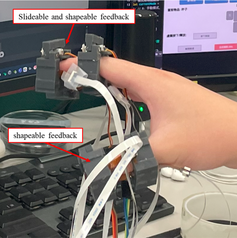
- 多點獨立控制:在手指的前後左右多個位置提供觸覺
- 連續變化:能模擬滑動、抓握等動態觸感
- 可穿戴:輕薄、舒適、不影響手部動作
- Multi-point independent control: Providing haptic feedback at multiple locations on the finger – front, back, left, right
- Continuous variation: Simulating dynamic sensations like sliding and grasping
- Wearable: Thin, light, comfortable, doesn’t restrict hand movement
而這套系統的開發,剛好讓我能夠完整地走過從技術選型、性能優化、硬體設計、軟體整合,一直到實際驗證的每一個步驟。
And developing this system allows me to walk through every step of the process – from technology selection, performance optimization, hardware design, software integration, all the way to actual validation.
Section 2: System Architecture | 系統架構
在確定了問題之後,接下來就是要去思考,我該用什麼技術來實現?
After defining the problem, the next question was: What technology should I use to make this happen?
我需要的致動器要夠輕薄、能獨立控制、反應速度夠快。所以我開始系統性地評估各種技術:電磁致動器輸出力夠,但線圈體積太大;壓電致動器反應快,但形變量太小;電液致動器需要12kV高壓,安全風險太高。
The actuator I needed had to be thin and light, independently controllable, and fast enough. So I started systematically evaluating different technologies: Electromagnetic actuators had enough output force, but the coils were too bulky. Piezoelectric actuators were fast, but their displacement was too small. Electrohydraulic actuators required 12kV high voltage – way too risky from a safety perspective.
最後我找到了嵌入式電滲透泵(EEOPs):它靠電場驅動液體流動,沒有機械運動零件、電壓相對安全(250V)、而且可以做得很薄。這項技術在2023年才剛開始出現在學術研討會上,還處於實驗室階段。
Eventually, I found Embedded Electroosmotic Pumps (EEOPs): They use electric fields to drive fluid flow, have no mechanical moving parts, use relatively safe voltage (250V), and can be made very thin. This technology had just started appearing at academic conferences in 2023 – it was still in the lab stage.
但是這裡遇到了第一個關鍵問題,研討會論文只說明了使用的材料跟架構,但是卻沒有說明怎麼製作
But here’s where I hit the first critical problem – the conference papers described the materials and architecture they used, but they didn’t explain how to actually make it.
學術論文會給你理論、會給你實驗結果,但不會告訴你「孔洞要開多大?」「導電圓要畫多大?」「孔洞之間要距離多遠?」這些實際製作時的參數。這些參數就像一個黑盒子,沒有配方,只能自己反推。
Academic papers give you theory, they give you experimental results, but they won’t tell you “How big should the holes be?” “What diameter should the conductive circles be?” “How far apart should the holes be spaced?” These actual fabrication parameters are like a black box – there’s no recipe, you have to reverse-engineer it yourself.
實驗設計法:田口方法解開未知領域
Experimental Design: Using Taguchi Method to Unlock the Unknown
我決定用田口方法來找出這些關鍵參數。這個方法的優勢是:如果我要測試4個參數、每個參數3個水準,完全測試需要3⁴=81組實驗。但用田口法的L9正交陣列,只需要9組實驗就能識別出主要影響因子。
I decided to use the Taguchi method to figure out these key parameters. The advantage of this approach is: if I need to test 4 parameters with 3 levels each, a full factorial experiment would require 3⁴ = 81 test runs. But using Taguchi’s L9 orthogonal array, I only need 9 experimental runs to identify the main factors that actually matter.
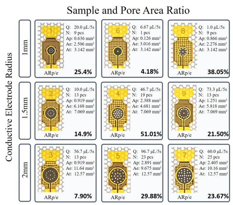
我在EasyEDA裡設計了9種不同的電極圖案,每種都是不同的參數組合:
- 孔洞直徑:0.3mm、0.4mm、0.5mm
- 孔洞間距:0.8mm、1.2mm、1.6mm
- 導電圓直徑:1.0mm、1.5mm、2.0mm
- 格線間距:1.0mm、1.5mm、2.0mm
I designed 9 different electrode patterns in EasyEDA, each one with a different combination of parameters:
- Hole diameter: 0.3mm, 0.4mm, 0.5mm
- Hole spacing: 0.8mm, 1.2mm, 1.6mm
- Conductive circle diameter: 1.0mm, 1.5mm, 2.0mm
- Grid spacing: 1.0mm, 1.5mm, 2.0mm
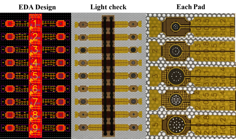
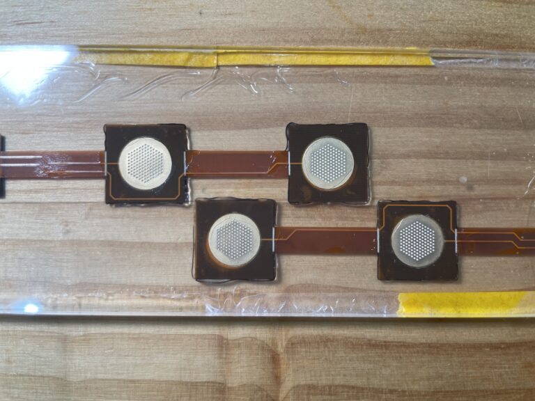
我把利用田口方法設計的電極布局,將這9種設計我全部排在同一片FPC上。這樣做的好處是:我可以一次製作出所有樣本,然後剪開來分別測試。這需要在EDA軟體裡仔細規劃排列方式,確保每個設計都能獨立切割使用,同時也要考慮電極的走線不能互相干擾。
I took those 9 electrode layouts designed using the Taguchi method and arranged them all on a single FPC board. The advantage of doing it this way is: I can fabricate all the samples in one go, then cut them apart and test them individually. This requires careful planning in the EDA software to arrange them properly – making sure each design can be independently cut out, while also ensuring the electrode traces don’t interfere with each other.
治具系統:確保組裝一致性
Fixture System: Ensuring Assembly Consistency
EEOPs的結構包含多層材料:FPC電極、GFF玻璃纖維膜、PI聚醯亞胺膜、PSA壓敏膠、導電層、矽膠覆蓋層。這些層必須精準對位,否則會影響電滲透效果。
The EEOP structure contains multiple layers of materials: FPC electrode, GFF glass fiber membrane, PI polyimide film, PSA pressure-sensitive adhesive, conductive layer, and silicone cover layer. These layers must be precisely aligned, otherwise it affects the electroosmotic performance.
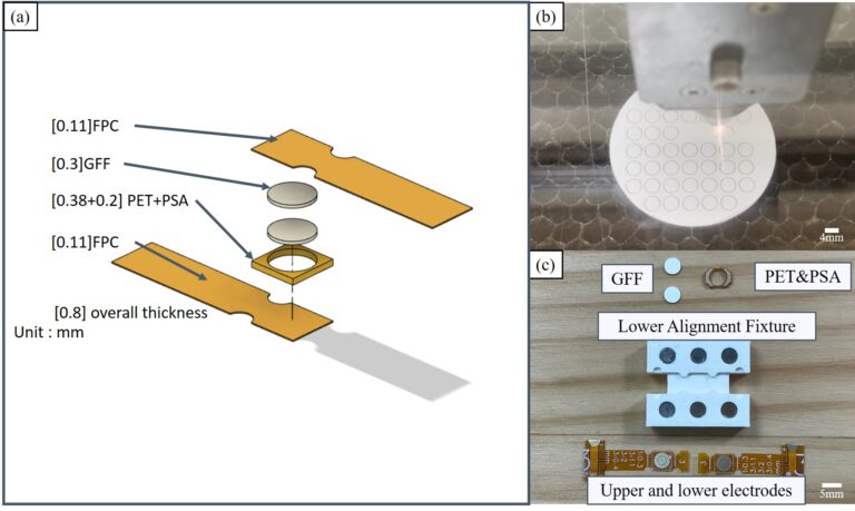
我設計了一套組裝治具系統,用FDM 3D列印製作。主要關鍵設計是:6個釹鐵硼強磁鐵(ø4mm × 3mm),分別嵌入治具的6個定位孔中。
I designed an assembly fixture system, fabricated using FDM 3D printing. The key design feature is: 6 neodymium magnets (ø4mm × 3mm), each embedded into 6 positioning holes in the fixture.
磁鐵的作用不只是固定,更重要的是提供均勻的壓緊力道。每次組裝時,磁鐵都會施加相同的壓力,確保PSA黏著層與電極間的緊密接合。這個標準化流程解決了手動組裝的偏差問題,讓每個EEOP單元的性能都能保持一致。
The magnets don’t just hold things in place – more importantly, they provide uniform clamping force. Every time you assemble, the magnets apply the same pressure, ensuring tight bonding between the PSA adhesive layer and the electrodes. This standardized process solved the deviation problems of manual assembly, allowing each EEOP unit to maintain consistent performance.
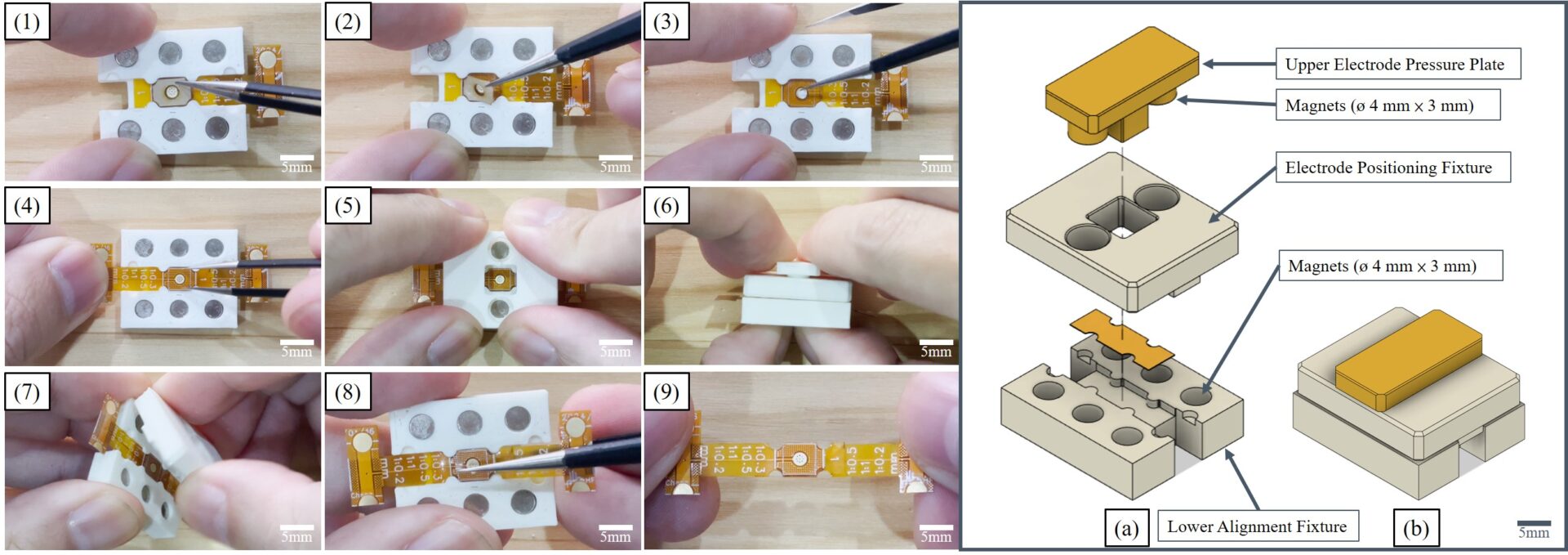
組裝過程需要非常嚴謹來實現一致性:一層一層對位、壓合、檢查。治具確保了每次對位的精度,磁鐵確保了壓力的一致性。這套系統讓我可以穩定地製作出性能一致的EEOPs單元。
The assembly process requires rigorous attention to achieve consistency: aligning layer by layer, bonding, checking. The fixture ensures alignment precision every time, and the magnets ensure pressure consistency. This system allows me to reliably fabricate EEOP units with consistent performance.
安全優先的實驗設計
Safety-First Experimental Design
在開始測試之前,我必須面對一個現實:EEOPs需要250V的驅動電壓。
這個電壓不會致命,但是安全而言我並不想碰觸到這樣的電壓。所以我設計了一套安全機制。
Before starting testing, I had to face a reality: EEOPs require 250V driving voltage.
This voltage won’t kill you, but from a safety standpoint, I really didn’t want to touch that kind of voltage. So I designed a safety mechanism.

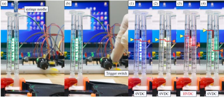
我用Arduino寫了一個控制程式,搭配ws2812b RGBLED硬式燈條,來顯示目前的驅動電壓狀況:
- 綠燈(8顆):待命狀態,安全 (0V)
- 藍燈(8顆):5秒準備期,讓我有足夠的時間遠離實驗區 (0V)
- 黃燈(3顆):高壓警告 (0V)
- 紅燈(3顆):250V開始驅動,維持5秒 (250V DC)
I wrote an Arduino control program paired with WS2812B RGB LED rigid strip to display the current driving voltage status:
- Green lights (8 LEDs): Standby state, safe (0V)
- Blue lights (8 LEDs): 5-second preparation period, giving me enough time to get away from the experiment area (0V)
- Yellow lights (3 LEDs): High voltage warning (0V)
- Red lights (3 LEDs): 250V drive starts, lasts 5 seconds (250V DC)
當我按下按鈕後,會開始倒數並且顯示藍燈,讓我可以知道該離開所有導電的東西,最後顯示黃燈告知即將開始高電壓驅動,以及驅動中的紅燈來顯示出危險狀態,結束後回到綠色,來展示狀態的安全性。
這樣的設計來自使用者的安全考量:人需要反應時間,而5秒足夠讓我從手完全離開任何導電物品。即使我在記錄數據、或者手上拿著工具,也有充足的時間放下東西。
When I press the button, it starts counting down and shows blue lights, letting me know to get away from anything conductive. Finally it shows yellow lights to indicate high voltage drive is about to start, and red lights during operation to show the dangerous state. After it’s done, it returns to green to show it’s safe again.
This design comes from user safety considerations: people need reaction time, and 5 seconds is enough for me to completely remove my hands from any conductive objects. Even if I’m recording data or holding tools, there’s plenty of time to put things down.
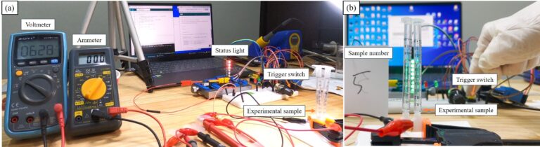
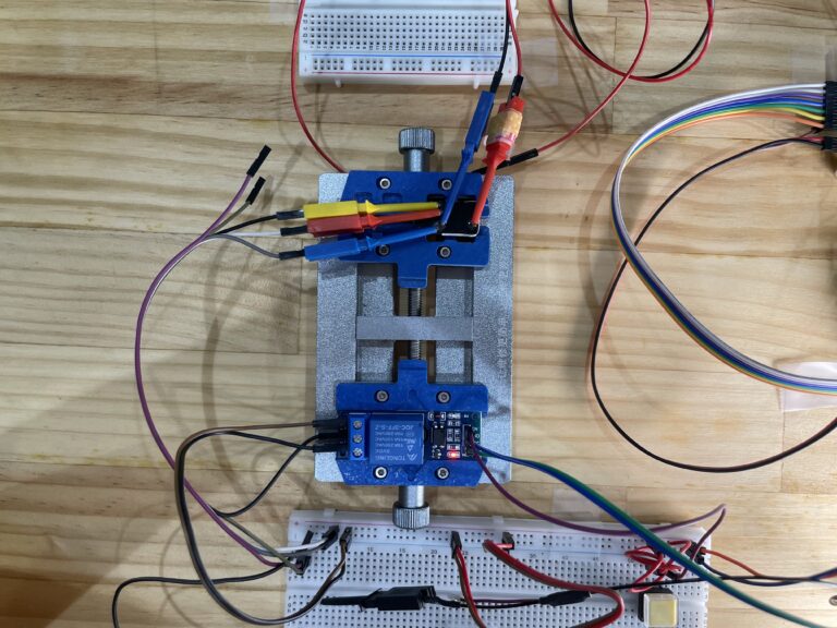
實驗的測試方法,用1mL注射器收集5秒鐘能泵送多少液體。每次測試,我按下按鈕、看到藍燈亮起,就轉身走開。等紅燈滅掉,亮起綠燈安全後,我才走回去讀取注射器上的刻度,然後記錄在實驗筆記本上。
每組參數我都測試3次,確保數據的可靠性。
For the testing method, I used a 1mL syringe to collect how much liquid could be pumped in 5 seconds. Each test, I’d press the button, see the blue lights turn on, and then turn around and walk away. Only after the red lights went out and the green safety lights came on would I walk back to read the scale on the syringe and record it in my lab notebook.
I tested each parameter set 3 times to ensure data reliability.
根據結果來說:樣本#5的流量最大,達到96.67μL/5s。樣本#8最差,只有1μL/5s。這樣的差異性,清楚的表現了參數組合的重要性。
Results: Sample #5 had the highest flow rate, reaching 96.67μL/5s. Sample #8 was the worst at only 1μL/5s. This variation clearly demonstrated the importance of parameter combinations.
更重要的是,透過數據分析,我找到了關鍵影響因子:導電圓直徑和格線間距(影響結構強度)。我成功定義出19.35%-32.857%的最佳面積比範圍,讓系統流量提升了188%。這個範圍成為後續設計不同尺寸EEOP時的明確準則。
More importantly, through data analysis, I identified the key influencing factors: conductive circle diameter and grid spacing (which affect structural strength). I successfully defined an optimal area ratio range of 19.35%-32.857%, which improved system flow rate by 188%. This range became a clear guideline for designing EEOPs of different sizes going forward.
將泵浦改成至動器的關鍵:0.25mm矽膠薄膜
The Key to Converting Pump to Actuator: 0.25mm Silicone Membrane
找到參數後,接下來要面對的是製作問題。EEOPs需要一層0.25mm厚的矽膠薄膜作為可變形的覆蓋層,但市面上根本買不到這個規格。
After finding the parameters, the next challenge was fabrication. EEOPs need a 0.25mm thick silicone membrane as a deformable cover layer, but this specification simply isn’t available on the market.
所以我只能自己做出0.25mm的矽膠薄膜。
So I had to make my own 0.25mm silicone membrane.
第一次嘗試,我用紙杯當模具。失敗。紙杯無法控制厚度,而且每次只能做一片,沒辦法批量生產,更沒有一個合適的載體來進行後續的組裝設計。
第二次嘗試,我用3D列印機(創想S1 Pro)印出模具,然後用壓克力板上下夾住。理論上可行,但實際測試發現:3D列印的精度不夠。0.25mm這麼薄的厚度,列印機的層高誤差就會造成矽膠厚度不均,有些地方太厚、有些地方太薄。當時的技術限制讓這個方法無法達到我需要的精度。
最後我想到了一個方法:用便條紙當墊片。
便條紙的厚度剛好是0.25mm。我把便條紙裁成框架形狀,放在3mm壓克力板之間,然後倒入矽膠。矽膠固化後,我就得到了厚度精確、表面均勻的0.25mm薄膜。
First attempt: I used a paper cup as a mold. Failed. The paper cup couldn’t control thickness, and I could only make one piece at a time – no way to mass produce, and no suitable carrier for subsequent assembly design.
Second attempt: I used a 3D printer (Creality Ender S1 Pro) to print a mold, then sandwiched it between acrylic plates. Theoretically viable, but actual testing revealed: the 3D printing precision wasn’t good enough. At 0.25mm thickness, the printer’s layer height error causes uneven silicone thickness – some areas too thick, some too thin. The technical limitations at the time meant this method couldn’t achieve the precision I needed.
Finally, I thought of a solution: using sticky notes as spacers.
Sticky notes are exactly 0.25mm thick. I cut the sticky notes into frame shapes, placed them between 3mm acrylic plates, then poured in the silicone. After the silicone cured, I got membranes with precise thickness and uniform surface at exactly 0.25mm.
這個解法展現了製作過程中最重要的思維:當高精度工具不可得時,找到生活中現成的精密物品。便條紙是標準化產品,它的厚度比3D列印機還要精準。而且這個方法可以批量製作,解決了生產效率的問題。
This solution demonstrates the most important mindset in the fabrication process: when high-precision tools aren’t available, find ready-made precision items in everyday life. Sticky notes are standardized products – their thickness is more precise than a 3D printer. Plus, this method allows for batch production, solving the production efficiency problem.
電路系統 Circuit System
EEOPs單元做好後,接下來要解決的是控制問題。我設計的觸覺系統需要12個獨立控制點(每根手指4點×3根手指)。如果每個控制點都需要獨立的驅動電路,系統會變得非常龐大且昂貴。
After the EEOP units were ready, the next problem to solve was control. My haptic system design requires 12 independent control points (4 points per finger × 3 fingers). If each control point needed its own independent drive circuit, the system would become extremely bulky and expensive.
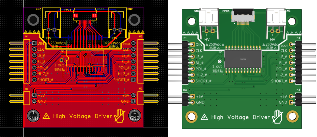
我在EasyEDA裡設計了HV513高壓控制模組的PCB。HV513是一顆8通道的高壓開關晶片,可以用低電壓邏輯信號(5V)來控制高電壓輸出(250V)。
I designed the PCB for an HV513 high-voltage control module in EasyEDA. The HV513 is an 8-channel high-voltage switch IC that can use low-voltage logic signals (5V) to control high-voltage output (250V).
電路設計中最重要的是安全隔離。我用JQC-3FF繼電器作為物理隔離元件:當系統斷電或停止觸發時,繼電器會強制將控制腳位接地,使輸出電壓在極短時間內降至安全水平(<1V)。這是完全放電設計,確保即使在異常狀況下,系統也不會留有殘餘高壓。
這種物理隔離的安全設計貫穿了整個系統:不只是保護實驗階段的我,更重要的是保護未來的使用者。
The most critical aspect of the circuit design is safety isolation. I used a JQC-3FF relay as a physical isolation component: when the system powers down or stops triggering, the relay forcibly grounds the control pins, bringing the output voltage down to a safe level (<1V) in an extremely short time. This is a complete discharge design, ensuring that even under abnormal conditions, the system won’t retain residual high voltage.
This physical isolation safety design runs throughout the entire system: it’s not just protecting me during the experimental phase, but more importantly, protecting future users.
軟體整合 Software Integration
硬體完成後,最後一步是軟體整合。我需要把Unity 3D引擎、Leap Motion手部追蹤、Arduino控制器、p5.js視覺化全部串接起來。
After the hardware was complete, the final step was software integration. I needed to connect Unity 3D engine, Leap Motion hand tracking, Arduino controller, and p5.js visualization all together.
老實說,這是我第一次用Unity。我本來的專業是機械工程和電路設計,3D遊戲引擎對我來說是全新的領域。但我需要Unity的物理引擎來模擬虛擬物體的碰撞和抓取,也需要它的渲染引擎來提供視覺回饋。
Honestly, this was my first time using Unity. My original expertise is mechanical engineering and circuit design – a 3D game engine was completely new territory for me. But I needed Unity’s physics engine to simulate collisions and grasping of virtual objects, and I needed its rendering engine to provide visual feedback.
我花了很多時間學習Unity的腳本系統、碰撞偵測、物理材質設定。Leap Motion的SDK整合也遇到不少問題,因為手部追蹤的座標系統跟Unity場景的座標系統需要仔細對應。我用Unity主要是為了提供物理引擎和手部抓取虛擬物品的視覺呈現,雖然整合過程充滿挑戰,但最終還是成功建立起來了。
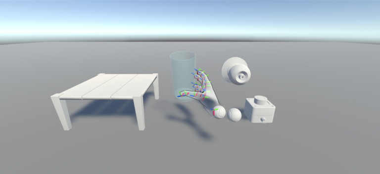
完整的系統架構圖 – Unity→安全按鈕 || p5.js → Arduino → HV513 → EEOP
最後,我成功建立了觸覺回饋系統:當虛擬手在Unity中接觸到虛擬物體時,使用者在抓握物品時持續按著按鈕。系統透過p5.js處理互動邏輯,Arduino接收信號並控制HV513模組,觸發相應的EEOP單元,使用者的真實手指就能感受到觸覺回饋。
I spent a lot of time learning Unity’s scripting system, collision detection, and physics material settings. Integrating the Leap Motion SDK also had quite a few issues, because the hand tracking coordinate system and Unity’s scene coordinate system needed to be carefully aligned. I mainly used Unity to provide the physics engine and visual presentation of hands grasping virtual objects. Although the integration process was full of challenges, I ultimately succeeded in building it.
Complete System Architecture – Unity → Safety Button || p5.js → Arduino → HV513 → EEOP
In the end, I successfully built the haptic feedback system: when the virtual hand in Unity touches a virtual object, the user continuously presses a button while grasping the item. The system processes interaction logic through p5.js, Arduino receives the signal and controls the HV513 module, triggering the corresponding EEOP units, and the user’s real fingers can feel the haptic feedback.
整個系統從未知技術參數反推、到安全實驗設計、到0.25mm製作挑戰、到治具標準化、到電路模組化、再到軟體整合,這不只是把技術堆疊在一起,而是讓機械、電路、軟體這三個不同領域的技術能夠真正一起運作。
這套系統實現了世界首創的12度自由度獨立觸覺控制,讓虛擬世界的觸覺回饋不再只是單點震動。這項突破發表在SCI Q1等級的國際期刊
這就是我擅長的:跨領域整合,並且在過程中解決所有實際的製作問題
The entire system – from reverse-engineering unknown technical parameters, to safety-first experimental design, to the 0.25mm fabrication challenge, to fixture standardization, to circuit modularization, and then to software integration – this isn’t just stacking technologies together, but making mechanical, circuit, and software technologies from three different domains truly work together.
This system achieved the world’s first 12-degree-of-freedom independent haptic control, making haptic feedback in the virtual world no longer just single-point vibration. This breakthrough was published in an SCI Q1 international journal: